Step
Action
Select the coordinate system to be used for the map. In this example the Swiss LV03 coordinate system is used but this can be replaced by any other coordinate system.
1
Open the GeoMoS Monitor and stop the service 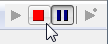 .
.
2
From menu bar select Configuration → Options.
3
Select the coordinate system you are using and press the Properties button.
The Coordinate System Manager opens.
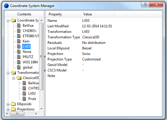
4
Select the Swiss LV03 coordinate system.
5
Start the service again .
.
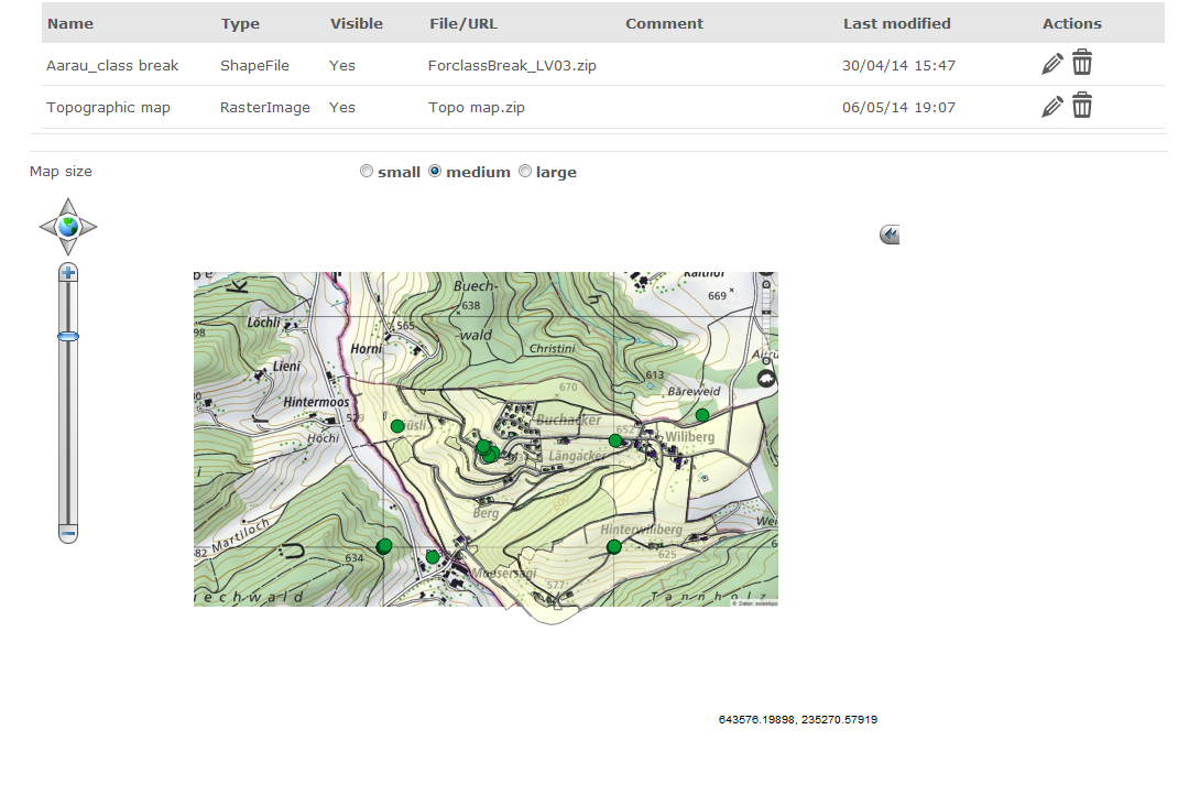
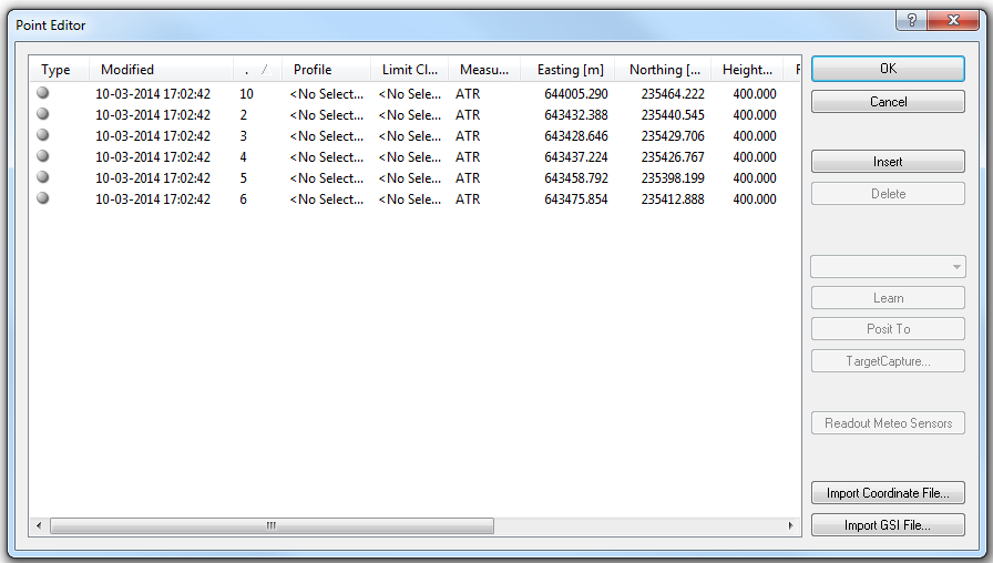
6
In the GeoMoS Monitor we can see sensor locations with Swiss LV03 coordinates.
In the next step we take the raster topographic map of the monitoring project and save the map as a JPG image.
Many of similar maps are already distributed with the world file but for our case we will perform georeferencing ourselves. For larger images, it is recommended to use uncompressed TIF files as they have faster performance.
7
Save the image as Raster_map.jpg.
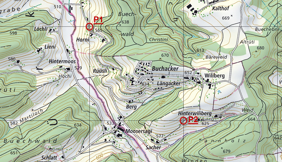
Select two points for which we know both the Swiss LV03 coordinates and the exact place on the image. We will use these points for georeferencing.
8
The real coordinates of the grid lines are known. Select P1 and P2 on the grid:
|
Point ID |
Easting |
Northing |
|
P(1) |
643000 |
236000 |
|
P(2) |
644000 |
235000 |
For further steps coordinate transformation software is needed. We will use an open source software QGIS but any other GIS software can be used.
We will create a world file that belongs to the raster data above.
9
Open the QGIS software and its Georeferencing tool from top menu in Raster → Georeferencer → Georeferencer.
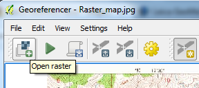
10
First, we add the raster image by selecting the open raster icon and point to a location of Raster_map.jpg on a disk.
11
The Coordinate Reference System Selector pops up and we select CH1903 / LV03. If your coordinate system is not listed here you can choose any other because the world file does not contain this information.
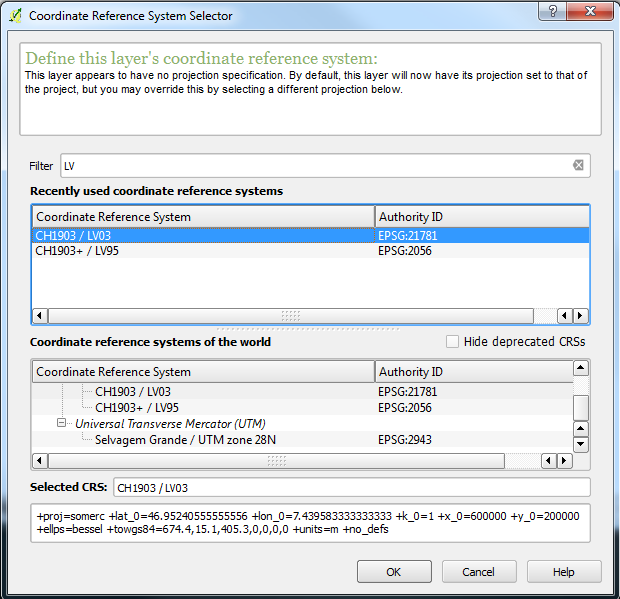
Press OK.
We need to add control points to the image. The crosshair pointer tool is already working so we can select a point by clicking on it on our map.
12
Select point P1 and enter the real coordinates from the Swiss LV03 map.
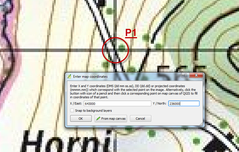
Press OK.
13
Repeat the procedure by pointing to the P2 location on the map.
14
Now define transformation based on the selected points P1 and P2.
![]()
15
Keep the default settings for transformation, enter the new name for the raster file and turn the Create world file check box on.
![]()
Press OK.
16
The world file containing the transformation is created locally on your system with the name Raster_map_modified.wld.
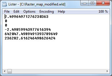
You can check the transformation parameters that are part of the WLD file.
17
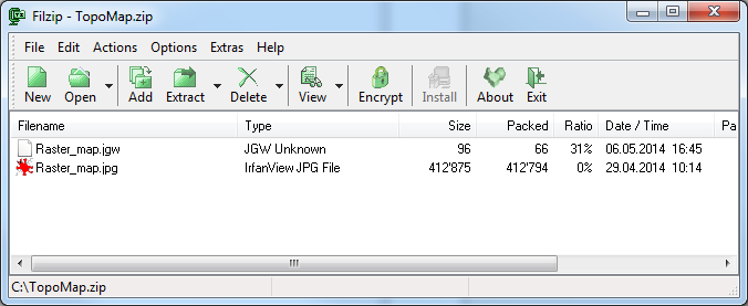
Modify the transformation file format so that GeoMoS Now! can use it.
-
Rename Raster_map_modified.wld to Raster_map.jgw
-
Create one ZIP archive that contains the JGW world file with the transformation parameters and the original raster image.
Our transformation is defined in TopoMap.zip archive.
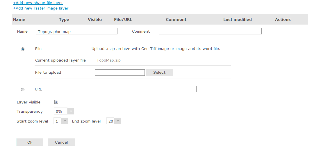
18
Go to GeoMoS Now!.
From the left menu open Settings → Maps and upload the ZIP file.